I. What is a Reducer?
In simple terms, a reducer can be described as a “speed reducer and torque amplifier.” Imagine the scenario of shifting gears in a car to climb a hill—the working principle of a reducer is similar. It converts the high-speed rotation of a motor into low-speed, high-torque output. For example, if a motor rotates at 1,500 RPM, the output shaft of the reducer might reduce this to 30 RPM. Though the output speed seems slow, the resulting torque can easily lift hundreds of kilograms—a remarkable feat!
II. Components of a Reducer
After understanding the concept, let’s explore its internal structure. A reducer consists of three core components:
- Gear Set: Similar to a bicycle’s transmission, it changes speed through meshing gears of different sizes, playing a critical role in speed adjustment.
- Bearings: As precision components, bearings ensure smooth rotation, reduce friction losses, and guarantee stable operation.
- Housing: Typically made of metal, the housing acts as a protective shield, safeguarding internal components from external interference.
III. Four Common Types of Reducers
- Gear Reducer
- Advantages: Robust, cost-effective, and high cost-performance ratio.
- Disadvantages: Relatively high operational noise.
- Applications: Widely used in industrial scenarios with low noise requirements, such as conveyor belts and mixers.
- Planetary Reducer
- Advantages: High precision, compact structure, and efficient transmission in limited spaces.
- Disadvantages: Complex internal structure, making manufacturing and maintenance challenging.
- Applications: Common in precision equipment like robotic arms and machine tools.
- Worm Gear Reducer
- Advantages: Self-locking feature for enhanced safety and high gear ratios.
- Disadvantages: Low energy conversion efficiency and higher energy consumption.
- Applications: Ideal for safety-critical equipment such as cranes and elevators.
- Harmonic Reducer
- Advantages: Zero backlash, precise positioning, and long service life.
- Disadvantages: Complicated repairs in case of failure.
- Applications: Specialized industrial scenarios requiring stability and precision, such as mining machinery.
IV. Five-Step Method for Reducer Selection
- Analyze Load Conditions
- Steady Load: Examples include conveyor belts and fans, where load remains stable.
- Impact Load: Equipment like presses and crushers generate sudden impact loads.
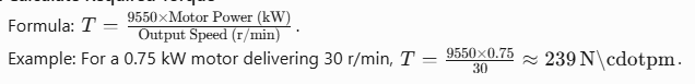
- Calculate Required Torque
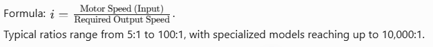
3.Determine Gear Ratio
4.Verify Power Rating
Select a model with a load capacity ≥ calculated value, adding a safety margin of 1.2–1.5x (e.g., torque × 1.2–1.5).
- Check Installation Dimensions
Confirm flange type (e.g., flange-mounted, shaft-mounted), dimensions, and shaft diameter to ensure compatibility.
V. Practical Case Study
Scenario: Selecting a reducer for a mixer. - Motor power: 5.5 kW, speed: 1,440 r/min.
- Required output speed: 60 r/min, load torque: 800 N·m.
- Calculate gear ratio: i=601440=24. Select standard ratio 25.
VI. Pitfall Avoidance Guide - Environmental Factors
- High-Temperature Environments: Use reducers with heat-resistant oil seals.
- Humid Conditions: Opt for waterproof reducers to prevent rust.
- Dusty Environments: Choose fully sealed designs to block dust ingress.
- Maintenance Tips
- Select appropriate grease types—incorrect choices negate lubrication benefits
- Replace lubricant within 200 hours of initial operation for long-term reliability.
- Cost-Saving Traps
- Avoid counterfeit reducers with recycled gears—they may fail in a tenth of the lifespan of genuine products.
By mastering these fundamentals, you’ll select the right reducers and avoid common pitfalls in real-world applications!